Simple 5V Serial Interface for Raspberry Pi 2 and 3
My goal for this project was to make a simple serial interface from the Raspberry Pi to devices with a serial interface with 5V logic. This is the case for many Transceivers, for instance from ICOM, and also the Roomba robotic vaccum cleaner, which I have. The Roomba was my immediate motivation, because its bumper sensors became always on, such that it didn't move forward anymore. So my thought was to use its serical interface to connect it to a Raspberry Pi, in which I then have a Python program running which controls it. In a way a new "brain" for the Roomba, and possibly new sensors too.
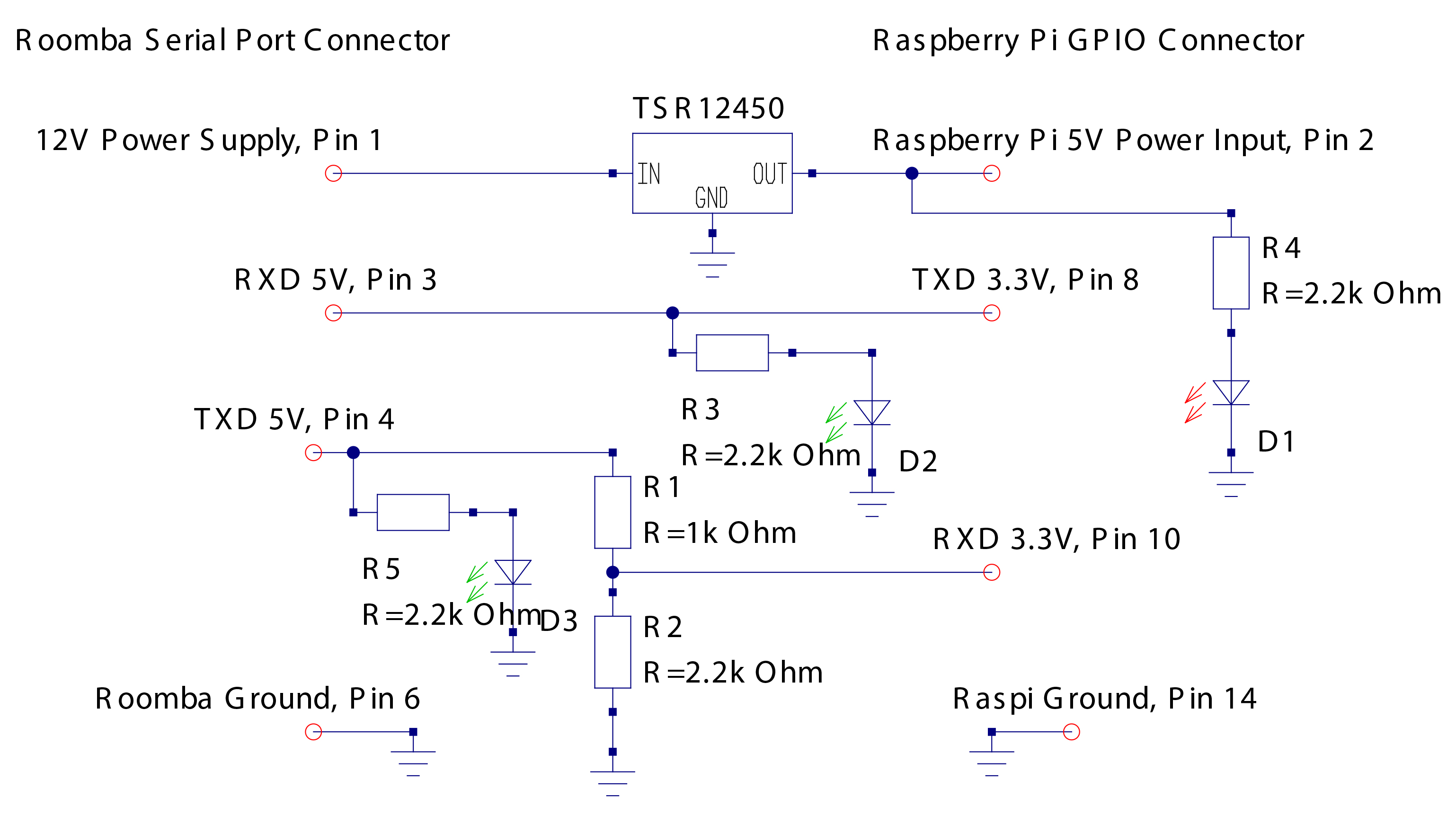
The Roomba not only has a 5V serial interface, but its 7 pol Mini Din socket also provides a 12V supply with abut 200 mA max. The Raspi needs exactly 5V at one of its 5V pins, with about 400 mA for the Raspi 2. So the 200 mA is not quite enough when using a linear voltage regulator. But fortunately, nowadays there are small and inexpensive switching regulators with an efficiency of over 90%, such that they also don't need a heat sink. I used the TSR 1-2450 from Traco Power, which only needs 3 pins (input, output 5V, and ground).
Two of the Raspi GPIO pins work as 3.3V serial interface. Fortunately, a 3.3V logic output can drive a 5V logic input directly with no problems. But for the reverse direction, from a 5V logic output to a 3.3V logic input, a voltage divider is needed to reduce the voltage to 2/3 of the 5V. This can be done for instance with a 1 kOhm resitor after the 5V logic output, driving a 3.3V logic input with a 2 kOhm resistor in parallel to it (see also sparkfun.com).
Hence the interface is really simple: A 5V switching power regulator, and a voltage divider of 1 KOhm and 2 kOhm resistors. Additionally I installed LED's in series of 2 kOhm resistors at the 5V putput of the regulator, and on each the serial input and output, to monitor its workings. The resulting schematic diagram can be seen in the picture. I used a small breadbord and an inexpensive row of sockets for the Raspi GPIO's and the 5V power supply. The resulting schematic is shown in Fig. RaspiInterfaceSchematic.pdf.
This link shows how the serial port of the Raspi can be accessed from the Raspberry Pi. In Python it is quite simple, for example:
import serial
import serial.tools.list_ports
ports=serial.tools.list_ports.comports()
print "Ports: ", ports
ser = serial.Serial('/dev/ttyAMA0',115200) # open Raspi GPIO serial port, speed 115200 for Roomba 5xx
#ser = serial.Serial('/dev/ttyAMA0',57600) # open Raspi GPIO serial port, speed 57600 for Roomba 3xx print(ser.name) #prints name of opened port, for checking
ser.write(b'\x80') #for writing
s=ser.read(..) #for reading
This link and this link show the pinouts of Raspi's GPIO's. See also a picture of the Raspi 2 and 3 GPIO on the right side.